The goal
Make wireless lan antenna find best signal area for specified (My) network.
Usability
Low, just for fun.
Parts
- TP-LINK MR3020 router flashed with OpenWrt
- MR3020 power cable and original power supply
- USB wireless card e.g TP-LINK TL-WN722N
- USB hub
- Yagi antenna
- camera tripod
- stepper motor (from old printer)
- gears (as above)
- signal wires
Code
Hardware
Media
Openwrt antenna rotator at work
Openwrt antenna rotator at work
Use Case
At the end of this page.
Description
Antenna
In this project I use Yagi antenna with modified cable, original was to heavy and caused rotating problems.
Plastic handle, shipped with antenna is also modified by adding plastic gear from stepper motor (got from old printer). Gear fits perfect on antenna handle, and thanks to cable ties, construction is more robust.
 |
|
|
|
|
|
| | |
| Thin cable, removed from other TP-LINK antenna. |
|
 |
| Gear mount is glued to plastic holder. |
 |
Gear and plastic holder, have holes for cable ties.
For more stable movement. |
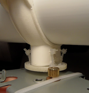
Camera tripod
This is a standard, cheapest camera tripod, I needed to make hole in the middle of camera grip, because stepper motor has long shaft.
 |
| Camera tripod with hole in the middle of camera grip. |
 |
| Stepper motor PM55l-048... |
 |
| Motor has accurate size. |
 |
| Some cable ties... |
 |
| At the end antenna on right place. |
 |
| Final |
Motor driver
If you want to know how to drive stepper motor by ULN2003, you can google it, there is a plenty of articles about.
ULN2003 is connected to attiny2313 on IO pins and attiny2313 is connected to MR3020 by RS232, no magic included.
More about this driver can be found in section HARDWARE on head of this article.
 |
| RS232 Stepper motor control. |
 |
| Ugly side. |
Power supply is provided by MR3020 power supply cable, which was been modified by changing USB socket to female pin connector.
 |
| Modified original MR3020 power supply USB cable. |
 |
| Female power connector. |
 |
| RS232 connector cable. |
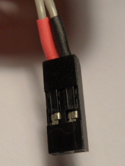
Stepper motor is connected to the board by the same female connectors. The red one is +5V, other ones are connected to attiny2313 logic outputs.
 |
| Stepper motor female connectors. |
 |
| Stepper motor control connected to MR3020 by RS232. |
|
|
For more info about RS232 on MR3020, follow this link.
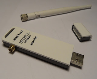 |
| External wireless USB adapter. |
 |
| USB hub and pendrive |
 |
| MR3020 + USB hub + external wireless + RS232 stepper motor control. |
 |
| Final |
 |
| Connection view. |
Use Case
I assume, that 'chanmon' is already compiled and installed on OpenWrt, and wireless interface name is 'mon0'.
Program has different types of operation:
- Scanning beacons from channel 5. Output: bssid, channel, signal strength.
chanmon -i mon0 -c 5
- Monitor one network without following channel from beacon. Following channels is ON by default
chanmon -i mon0 -c 5 --bssid XX:XX:XX:XX:XX:XX --nofollow
- Track signal from one network. Antenna step delay is set to 300ms. Antenna will scan whole area (step from 00 to 90), and then go back to best signal position.
chanmon -i mon0 -c 5 --bssid XX:XX:XX:XX:XX:XX --nofollow --track --delay 300
 |
| Sample output in '--track' mode |
Tracking output info
signal at 0 is -48, count 3
signal at 1 is -47, count 3
signal at 2 is -48, count 3
signal at 3 is -49, count 3
signal at 4 is -49, count 3
signal at 5 is -49, count 3
signal at 6 is -50, count 3
signal at 7 is -52, count 3
signal at 8 is -52, count 3
signal at 9 is -51, count 3
signal at 10 is -49, count 3
signal at 11 is -47, count 3
signal at 12 is -46, count 3
signal at 13 is -45, count 3
signal at 14 is -45, count 3
signal at 15 is -44, count 3
signal at 16 is -44, count 3
signal at 17 is -43, count 3
signal at 18 is -44, count 3
signal at 19 is -43, count 3
signal at 20 is -43, count 3
signal at 21 is -42, count 3
signal at 22 is -42, count 3
signal at 23 is -42, count 3
signal at 24 is -42, count 3
signal at 25 is -42, count 3
signal at 26 is -43, count 3
signal at 27 is -43, count 3
signal at 28 is -43, count 3
signal at 29 is -50, count 3
signal at 30 is -45, count 3
signal at 31 is -44, count 3
signal at 32 is -45, count 3
signal at 33 is -44, count 3
signal at 34 is -46, count 3
signal at 35 is -48, count 3
signal at 36 is -51, count 3
signal at 37 is -50, count 3
signal at 38 is -49, count 2
signal at 39 is -53, count 3
signal at 40 is -48, count 2
signal at 41 is -47, count 3
signal at 42 is -46, count 2
signal at 43 is -45, count 3
signal at 44 is -45, count 3
signal at 45 is -44, count 3
signal at 46 is -44, count 3
signal at 47 is -60, count 3
signal at 48 is -52, count 3
signal at 49 is -45, count 3
signal at 50 is -46, count 3
signal at 51 is -45, count 3
signal at 52 is -48, count 3
signal at 53 is -46, count 3
signal at 54 is -48, count 3
signal at 55 is -49, count 3
signal at 56 is -49, count 3
signal at 57 is -51, count 2
signal at 58 is -50, count 3
signal at 59 is -50, count 3
signal at 60 is -49, count 3
signal at 61 is -49, count 3
signal at 62 is -48, count 3
signal at 63 is -46, count 3
signal at 64 is -45, count 3
signal at 65 is -45, count 3
signal at 66 is -44, count 3
signal at 67 is -44, count 3
signal at 68 is -44, count 3
signal at 69 is -44, count 3
signal at 70 is -45, count 3
signal at 71 is -46, count 3
signal at 72 is -48, count 3
signal at 73 is -49, count 3
signal at 74 is -49, count 3
signal at 75 is -50, count 3
signal at 76 is -51, count 3
signal at 77 is -50, count 2
signal at 78 is -50, count 3
signal at 79 is -57, count 3
signal at 80 is -53, count 3
signal at 81 is -55, count 3
signal at 82 is -51, count 3
signal at 83 is -53, count 3
signal at 84 is -53, count 3
signal at 85 is -52, count 3
signal at 86 is -50, count 3
signal at 87 is -48, count 3
signal at 88 is -48, count 3
signal at 89 is -48, count 3
Best signal -42 at 21
Packet sum 265, avg 2
After correction, best signal -42 at 21
Widest range  from 21, to 25, center is 23
Maximum is in the wider range
Setting center from wider range


Haha.. Nuts
ReplyDeletevery good project, id like it. Can you please advise me how to make it on arduino uno r3
ReplyDeleteHello,
DeleteHardware part (stepper motor driver) you can do very easily:
1. http://assiss.github.io/arduino-zhcn/cn/Tutorial/MotorKnob.html
2. Add serial communication like on my other post http://morethanuser.blogspot.com/2012/10/rs232-stepper-motor-control-attiny2313_22.html
3. Connect to OpenWrt, run my program, and if you done everything right, it will be working.
Ad.3 I don't have an Arduino, but I think, you can connect it pin-by-pin to OpenWrt (like I did), or over USB, Arduino should have something like usb<->rs232 controller. After connecting to OpenWrt, you should be able to see and talk to serial port of your Uno R3.
If your question was about doing everything on Arduino, this is nearly (but not) impossible. You should have wireless module with monitor option, and do some heavy coding to get signal strength data from packets. I don't know if 16MHz of your Uno R3 can make it.
Regards,
Igor.
Very cool! Actually, I have a use case, where it is actually practical. We just bought an old caravan. I've seen that it is common on campsites to have wifi, but usually one antenna covering a large area. So, my idea was to replace the old TV antenna with a fairly broad-spectrum Yagi, and have three radios, basically one wifi for the internal Wifi network, one for the external network and an LTE modem if no Wifi is available. Then, scan for the strongest signal whether that may be wifi or LTE. I can connect the antenna cable based on whether I'm scanning for either.
ReplyDeleteI was thinking about an OLinuXino board of some sort, with their GPIOs for the motor, an onboard Wifi, and a USB LTE modem and USB Wifi. Does that sound like a good idea?
Hi, sure it sounds like a good idea! Basically if you have some linux board and have access to gpio and e.g. usb to connect your modem/wifi it's always doable.
DeleteIf you manage to create this rotator, send some photos or maybe describe whole process to share with others, good luck!
I know this is a old post but curious if you ever got it going .I'm looking to build something similar .basi basically I have a WE826 router with a M.2 Serria Wireless MC7455 Modem installed in it .The WE826 is setup with 2 wifi antennas and 2 LTE Antennas .these come with the single diode antennas. But I have 2 directional wideband antennas setup for MIMO .I can get 30-50mbps down from a tower about 5 miles out with no line of sight. These are 15dbi panels(makes sure you get quality antennas and use as little as possible LMR400 Coaxiable Cabl e as every foot you loose dbi you can not use regular Coaxiable cable. Cable needs to be 50 0hms. Dual antennAn allows for MIMO and Carrier Aggregation basically can bond 2 bands together or 2 connections of same band if the tower your pointing at supports it) I have a couple different Sims for different carriers and want to switch between them without ckimbcli on the roof and trying info to find other tower. Also father in law has same setup an lives in RV and moves every 28 days. So I've got to get a stepper motor strong enough to handle the weight of two antennas. I think I can figure the rest out. I'm a computer programmer so creating/modifying your code should be simple. Was considering a raspberry pi that's powered by PoE can even convert the pi into the router and attach my m.2. Modem and have it all in one box outside with the Antennas mounted to the front of the box. I could then get the tilt and azimuth and save it to return back too .Controlling it all over WiFi or ethernet. With web portal .My main question is there a stepper motor mount that supports tilt or would I just need to get something like a gimbal base. As I would have a second stepper that adjusted tilt which I could just have another swival joint to use for the tilt but locking it in place might get trickey. So a gimbal base and I might look into the motors used for controlling gimbals like on a for drone you can control where it's looking .then hook that all up and that would handle all directions I needed. Will take a look at your code to get some ideas on calculating signal from both Antennas for the best combined strength. Thanks for the article gave me lots of inspiration!!
DeleteHi Thomas,
DeleteIt was just-for-fun project, and comparing to what you want to build, both of my hardware and code looks very rudimental :). I really encourage you to build it! You can be surprised how often "simple things" can be very complicated at the end, but always you'll ending this battle with some additional knowledge and skills.
About tilt sensor - I would go with some external one, because if you use stepper with tilt, you can be sometimes not aligned with antenna movement e.g. if you use belts instead of gears in moving mechanism.
Do your sim providers support roaming? If so, you could mount your antennas at fixed position pointing to cell tower with strongest signal and just connect to various providers using roaming. In general, inside the country it shouldn't be additionally charged, but I don't know if there are any bandwidth restrictions.
Despite roaming in your case is possible or not, I really keep my fingers crossed for your idea and whole process of engineering, programming and testing! It sounds like a lot of fun!
Regards,
Igor.
I read that Post and got it fine and informative. https://techvisionelectronics.com/product/channel-master-antenna-rotator-cm-9521aantenna-rotor/
ReplyDelete